#1
Creating new connection types
Description
This tutorial covers how to create new connection types, how to associate a numbering format to them, and save them to your symbol library.
Topics covered
Create connection, connection type, connection numbering, connection numbering format, orthogonal, connection tools
Video version
NOTE: This tutorial video was created using an older version of SkyCAD.
Ribbon buttons' appearance and positions may differ if you're using version 1.3.25 or higher.
Thank you for your patience while we update this tutorial.
Amendment
If you're using the Advanced or Pro license, when defining your new connection symbol properties (at timestamp 1:10 in the video), you will want to set the Net Branch Class property to Single Wire.
This is required for wire lists and harnesses to work.
Related Tutorials
- Customizing numbering (3:00)
- Replace connection type (1:00)
Written version
Introduction
If you want connections which have different appearances and/or numbering formats, follow this tutorial to create a new connection type.
Minimum steps
These are the minimum steps recommended to create a new connection:
- Select any connection symbol, either on a sheet or in the symbol library, go to the Connection Tools tab and select Create new connection
- Define a name and click OK
- Optional: Select the connection in the tree view, go to the Connection Tools tab and select Explore connection properties, Set connection text properties and/or Set numbering format as required. For details of each, see below.
- Select the connection in the tree view, go to the Home tab, select Save As and follow the prompts to save the connection
Explore connection properties
To explore and/or edit the properties of the connection, either explore the properties of the connection in the tree view or select the connection in the tree view, go to the Connection Tools tab and select Explore connection properties.
- Drawing color: Defines the color of the connection
- Line Style: Plain, Dotted or Axis
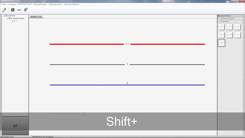
- Orthogonal (can be overridden by holding SHIFT when inserting a connection):
- Full: Connections can only be drawn in vertical and horizontal directions (up, down, left, and right)
- Partial: Connections can be drawn in vertical, horizontal and 45° diagonal directions
- None: Connections can be drawn at any angle compatible with the main grid
- Connection dot size: The dot size when three connection segments are joined

- Text offset: Defines how far away from the connection the connection text will be
- 0.00 mm / 0.000 in =
- 1.00 mm / 0.039 in =
- 0.00 mm / 0.000 in =
- Minimal length to show number: If a connection segment is less than this value, connection texts (wire/net numbers) will not display
- Show dotted when external: If this checkbox is checked, then when one of these connections connect two components together which are assigned to totally different locations, the connection will appear dotted
- Width: The thickness of the connection
- Net class: Must be defined for net (and wire) numbers to be generated. When a new connection type is created, a new net class is automatically created and set in the Net class property. Double-click the cell to choose a different net class if you wish, which will delete the automatically created net class once the new connection is saved.
(See Difference between nets and single wires section below.) - Net branch class: Always set this to Harness branch or Single wire (or custom Single wire sub-class you have created), whichever makes more sense. This is required for wire lists and harnesses to work properly, should you have the relevant license.
(See Difference between nets and single wires section below.) - Printable: When this is checked, the connection will be printed when you print or export to PDF.
- Default part number: If you would like a single wire catalogue part assigned to any single wires associated with these connections, enter that part number in here.
- Priority connection: Check this checkbox if you want this connection’s net to take precedence with regards to numbering should this connection’s net be connected to a different net class, most likely via a flow-through element.
Set connection text properties
To set connection text properties, select the connection in the tree view, go to the Connection Tools tab and select Set connection text properties.
This is where you change what information is displayed on the connections and the appearance of that text.
However, it does not change the numbering format associated to this connection, which will be addressed in the Set numbering format section below.
By default, new connections are set to display the net number, not the single wire number(s).
The difference between nets and single wires is addressed in the Difference between nets and single wires section below.
To change what text will be displayed, select the Value cell, go to the Home tab and de-select <A> Process property queries.
At that point, you should see <r:Parent.GetNet.Number> in the Value cell, which displays the net number associated to the connection when it is used in a schematic.
If you would like the single wire number to be displayed too, add <r:Parent.GetNetBranch.DisplayedLabel> to the query.
If you would like other single wire information displayed, such as wire size or color, use the same query, substituting DisplayedLabel for the name of the property you would like to query, omitting spaces, e.g. <r:Parent.GetNetBranch.WireSize>.
If you have any trouble whatsoever, please post on the forum describing what you need.
We are very responsive on the forum and are happy to help.
Difference between nets and single wires
A net is not a real-life object, but can be considered as “a logical group of connections”, or “an equipotential group”.
By default, connections in SkyCAD show the net numbers, e.g. 1, 2, 3 and 4 in the example below:
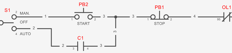
Notice how all the connections between PB2, PB1 and C1 all show “3”.
This is the net number “3”. Double-clicking a connection reaches the net.
To achieve the wiring between those 3 devices, at least 2 wires must be used.
Some companies may label both of those wires the same (e.g. 3), since they are connected together and thus carry the same potential.
Other companies may want those wires to have different numbers, even though they have the same potential (or “net” in SkyCAD terms). If this is you, see the Wire Lists & Single Wires tutorial.
Set numbering format
After setting the connection text properties, you may want to set the numbering format by selecting Set numbering format from the Connection Tools tab.
This will set the numbering format of the net class defined in the Net Class property.
(If, instead, you want to define the numbering format of the net branch defined in the Net Branch Class property, follow Creating a numbering format & assigning it to a class tutorial to assign a numbering format to that net branch class.)
By default, the numbering format Value will be <r:GetClass.GetRoot><#>, which will, in most cases, simply number the nets 1, 2, 3, etc.
The numbering format can be customized by following the Customizing numbering tutorial.
Save
Finally, select the connection in the tree view, go to the Home tab and Save/Save As.
Follow the prompts to save the connection symbol to your symbol library.
After that, it will be ready to insert.
Modify an existing connection symbol
There are two different ways to modify a symbol:
- Using Open Block
- In-context
Using Open Block
This method is preferred, as it allows you to change more than the in-context method.
Also, if you don’t want the modifications to affect existing instances of this symbol (i.e. existing projects/systems) you must use this method to create a new revision of the symbol before making the modifications, so existing instances using the previous revision of the symbol will be unaffected.
- Right-click on the symbol and choose Open Block
- If you don’t want the modifications to affect existing instances of the symbol, close the current revision of the symbol, create a new revision, then make the modifications
- If you want the modifications to affect existing instances of the symbol, proceed to make the modifications
- Close the tab (named after the symbol), saving the changes when prompted
If you followed step 3 above and wanted to see those changes reflected in your current project, close and re-open the project.
In-context
This method is best used when you want to make a minor modification to the symbol and don’t mind that modification occurring on existing instances of the symbol (i.e. existing projects/systems, even if their revisions are closed).
After the symbol is inserted onto a sheet, make the desired modifications, right-click on the symbol and choose Save.
To see those changes reflected in your current project, close and re-open the project.
Related Tutorials
- Customizing numbering (3:00)
- Replace connection type (1:00)