Adding connectors to components
#1
Adding connectors to components
Description
In this tutorial you'll learn how to assign connection ports to connectors in the block generator.
If you haven't seen the Block Generator tutorial, please watch that first, then come back to this tutorial.
Topics covered
Block generator, high-density, connectors, built-in connectors, assign to connector
Main content
Introduction
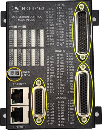
Some components have connectors, such as this Galil RIO-47162:
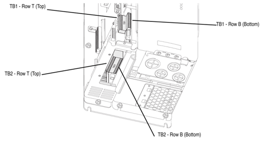
Some components have built-in terminal blocks, such as this Allen-Bradley PowerFlex 700S drive:
In both cases, these connectors or built-in terminal blocks should be considered as “connectors” in SkyCAD, so we’ll refer to both as “connectors” going forward.
On the schematics, on the block, you may wish to show:
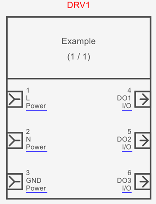
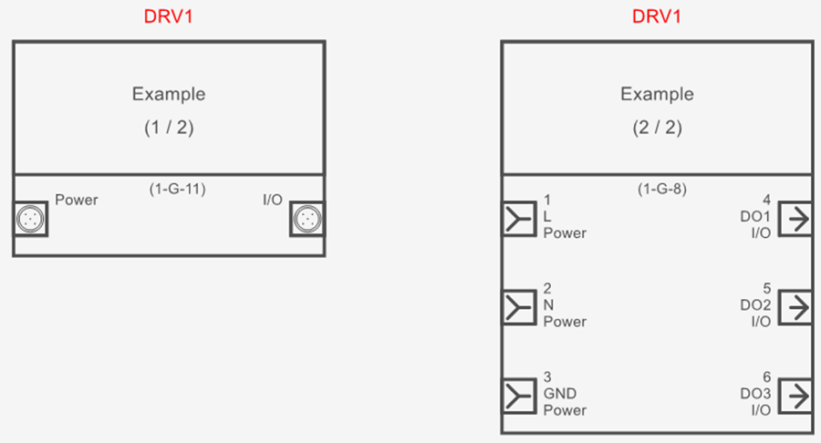
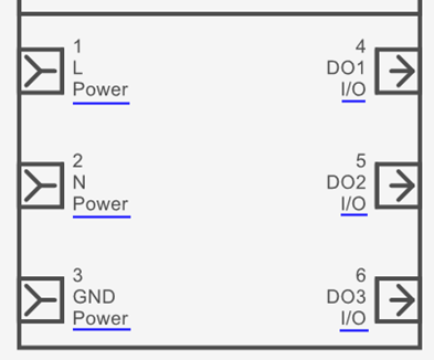
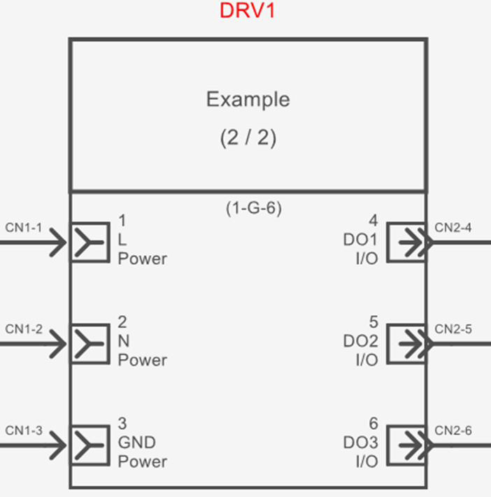
(Scenario 1) the individual ports as normal, but also note to which connectors the ports belong (e.g. “Power” & “I/O” connectors underlined in blue below):
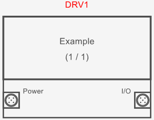
(Scenario 2) only the connectors, not the individual ports (e.g. “Power” & “I/O” connectors below, each of which have several pins which are not detailed here):
or (Scenario 3) scenario 1 and 2, but on two separate blocks linked together (e.g. single line diagram and detailed schematics):
Assigning connection ports to connectors
Regardless of which scenario best describes your needs, the recommended first step is to properly add all the individual connection ports to the component in the block generator, as this will set you up for success for your current project and future projects (where your needs may differ from your current project).
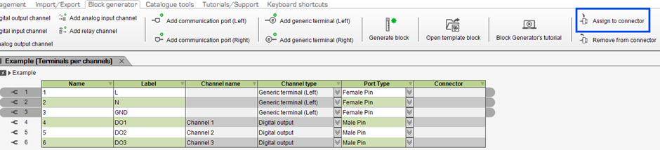
Once you have added all connection ports to your component in the block generator, use SHIFT or CTRL to select the connection ports which belong to a single connector, then select Assign to Connector from the Block Generator tab:
In the dialog box which pops up, go to the Create/Add tab and select New Connector to add a new connector the component.
Expand the properties of the connector to check the Virtual Part property (so the connector does not appear in parts lists) and change the Tag if desired.
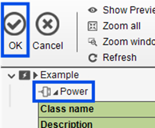
Select the connector (e.g. Power), then click OK:
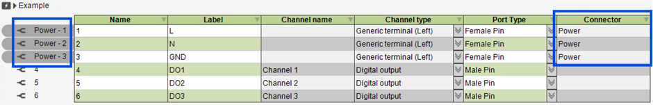
The selected connection ports will be assigned to the connector:
(If you do not see the Port Type or Connector columns in the block generator, unhide them by following this tutorial, starting at 0:35. If you still do not see them, kindly let us know on the forum.)
Repeat the above steps as required.
E.g. we have assigned ports 4-6 to another connector called I/O: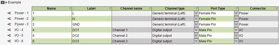
Then, follow the steps in scenario 1, 2 or 3 below.
Scenario 1: Show the individual ports and note to which connectors the ports belong
In some cases, depending on when you first installed SkyCAD, the connector tags (underlined in blue below) may automatically appear beside the ports:
If that is the case for you, skip ahead to the “Pin Matching” sub-section of this tutorial.
If that is not the case for you:
Download and install the latest version of SkyCAD (if you’re using a shared environment, ensure others install the latest version too)
Once you (and anyone sharing the same environment) are done working for the day, create a new topic on the forum and attach a zip file of your Standard Environment folder.
Note: your privacy is safe. Only SkyCAD staff can see files you upload to the forum.
We will make the relevant changes to your environment as soon as possible (so connector tags are shown where applicable) and send it back to you via the forum.
Pin matching
Often, in reality, mating connector pin numbers and component connector port names will match, e.g. pin 5 of a mating connector needs to connect to port 5 of the component connector.
SkyCAD’s Component Renumbering process changes the mating connector pin numbers to match the component connector port names.
For example, if you insert connector pin symbols (CN1 & CN2 pins below) so they are directly connected to a block’s ports:
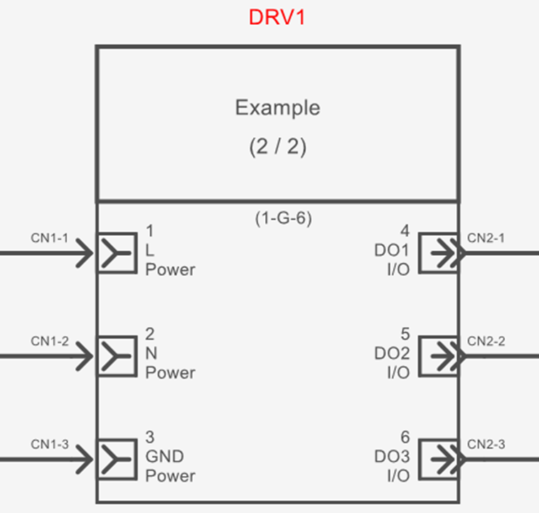
and the connector pin numbers are different to the component’s connection port names (e.g. CN2-1 is connected to port 4, CN2-2 is connected to port 5 and CN2-3 is connected to port 6), those connector pins are considered to be “unmatching”.
A list of all unmatching pins can be found by selecting the project/system in the tree view, going to the Show tab and selecting Unmatching connector pin pairs.
Running Component Renumbering (or Renumber All) from the Renumbering Process tab will display a message box:
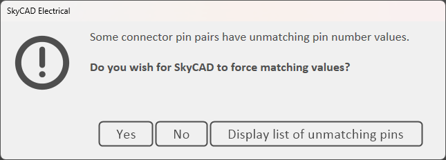
Selecting Yes will change connector pin numbers to match component connection port names (i.e. CN2-1 renumbered to CN2-4, CN2-2 renumbered to CN2-5, CN2-3 renumbered to CN2-6):
Selecting No will not change the unmatching connector pin numbers but will continue with the rest of the renumbering process.
Selecting Display list of unmatching pins will show you which pins are unmatching.
If you want to allow a certain connector’s pins to be unmatching and remove them from the Unmatching connector pin pairs list (thus not letting those pins trigger the message box when running Component Renumbering), explore the properties of the connector and check the Allow Unmatching Pins property.
Visually grouping ports of the same connector together
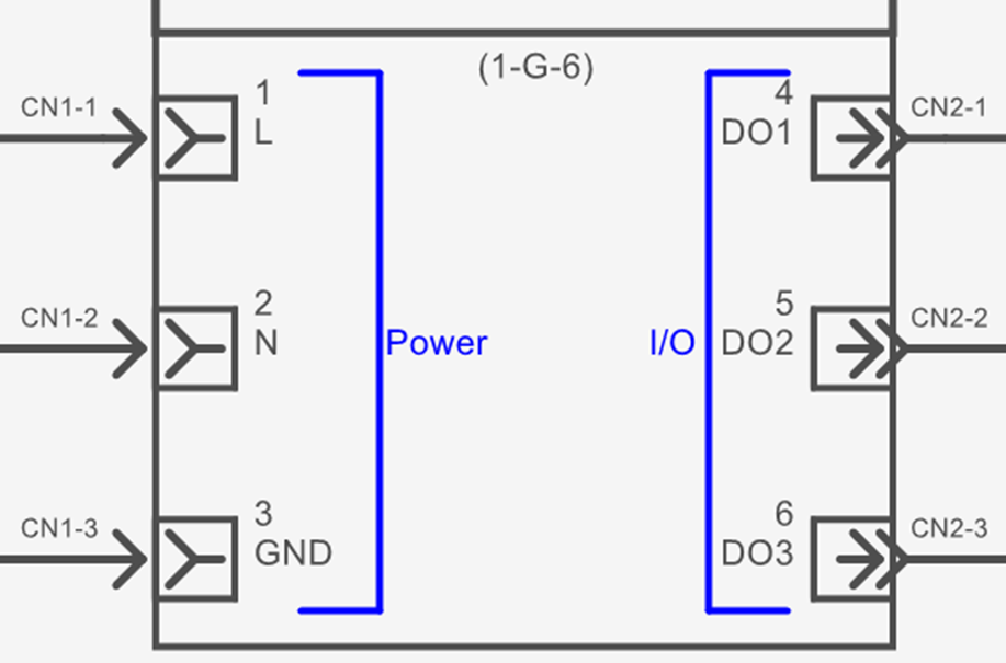
If you would like to visually group the ports associated to connectors together on the block (e.g. blue lines and text below):
then follow these steps:
Right-click on the entire component block and choose Open Block to open the block in editing mode
If you do not want the modifications to affect existing instances of the block, close the current revision of the symbol, create a new revision, then make the modifications
If you want the modifications to affect existing instances of the symbol, proceed to make the modifications
Use the tools in the Drawing tab to draw the modifications you wish to add
Optionally, delete the [Connector Tag] text attributes if you wish
Close the tab (named after the symbol), saving the changes when prompted
If you followed step 3 above and wanted to see those changes reflected in your current project/system, close and re-open the project/system.
Scenario 2: Show only the connectors, not the individual ports
For each connector you wish to represent, add a generic terminal to the component via the Block Generator tab.
These generic terminals will be used to represent the connectors.
Then, define the Name and Port Type properties for each generic terminal as desired.
The Name should be the name of the connector, e.g. Power, I/O, X1, TB1, etc.
Finally, use CTRL or SHIFT to select the generic terminals (connectors) you wish to appear on the block and select Generate Block from the Block Generator tab, then follow the prompts.
(The Block Generator tutorial at 5:57 shows how to generate blocks for selected terminals only.)
Scenario 3: Scenario 1 and 2, but on two separate blocks (e.g. single line diagram and detailed schematics)
Follow the steps in scenarios 1 and 2 to generate two separate blocks: a block showing the individual ports and a block showing only the connectors.
After inserting the blocks into the project, link them together as shown in the Block Generator tutorial at 7:19.
Related tutorials
- Block Generator (8:22)
- Adding Port Types (6:00)
- Linking symbols together (2:38)
- Using connectors (5:02)