Creating/modifying symbols and blocks
#1
Creating/modifying symbols and blocks
Description
This tutorial covers how to make your own custom symbols and blocks.
Topics Covered
Create new symbol, grid, sub-grid, snap to sub-grid, connection points, drawing icons, create graphical block, insertion point, symbol type, tag, connection point numbers, modify symbol, open block.
Video Version
NOTE: This tutorial video was created using an older version of SkyCAD.
Ribbon buttons' appearance and positions may differ if you're using version 1.3.25 or higher.
Thank you for your patience while we update this tutorial.
Related Tutorials
- Drawing tools overview (9:31)
- Showing component properties around a symbol (2:25)
- Catalogue tools (12:56)
Written Version
Introduction
If you do not find a symbol you need in the Symbol Library, you can create your own symbol by:
- modifying a similar symbol and doing a Save As (see the Modifying a symbol section below),
- creating it from scratch by following this tutorial or
- creating a catalogue part and block at the same time using the block generator (best used for more complex components with I/O)
In either of the first two cases, you will want to go to the Drawing tab and ensure Show Sub-Grid, Snap to sub-grid, Show connection points and Show empty attributes are all on.
The large dots are the grid and the small dots are the sub-grid.
Once you’re done, Show Sub-Grid and Snap to sub-grid can be turned off if you wish, but Show connection points and Show empty attributes are strongly recommended to be turned off to avoid accidentally clicking and dragging connection points or empty attributes.
Creating a symbol from scratch
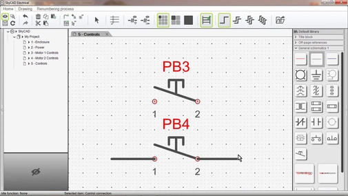
On a sheet, draw the desired symbol using the Drawing tools, ensuring that the place where you would want wires to connect to are on the main grid, i.e. the large dots.
Once you're done, click and drag to select all the objects of the symbol, then go to the Drawing tab and select Create graphical block.
When prompted to define an insertion point, click OK, then click to define the desired insertion point.
The insertion point is where the mouse cursor “grabs” the symbol when preparing to insert it onto a sheet from the symbol library.
(The insertion point must be on the main grid, i.e. the large dots.)
When prompted to define the type of element the block will represent, click OK, then choose the desired class and click OK.
(If you don’t see the class you want, follow the Catalogue Tools tutorial to create it.)
At this point you will notice all drawing objects have been grouped together and a WorkID text attribute has appeared above the symbol, which will usually display the Tag of the component associated with the symbol. Move the text attribute to the desired position.
Finally, select the symbol, go to the Drawing tab, select Add connection point and insert connection points wherever wires should be able to connect to this symbol.
(As mentioned earlier, the connection points must be on the main grid, i.e. the large dots.)
If you need to move some drawing objects so the connection points will be where you want them, select the symbol, go to the Drawing tab and select Explode graphical block to go back to where you need to select Create graphical block once you’ve made the changes you want.
If you’d like to change the default connection point names (which are 1, 2, 3, etc.), double-click on the connection point and set the Default Label property as you wish.
Those default labels will not affect this symbol, only future instances of this symbol you insert, once you save it.
If the symbol you’ve created represents normally open (NO) or normally closed (NC) contacts, select both connection points (hold CTRL when selecting the second connection point), go to the Drawing tab, select Define as NO contact, Define as NC contact or Define as PWR-NO contact (for power normally open contacts, such as the main poles of a contactor), then click OK.
If your symbol represents multiple NC and NO contacts, repeat these steps as necessary.
If you’d like additional text attributes, select the symbol, go to the Drawing tab and select Component property or Add cross-reference text.
If you’d like to add a custom query text attribute, go to the Drawing tab and select Text to add the text attribute, then link the text attribute to the symbol using Link With. (Let us know on the forum if you want help with the custom query.)
Finally, select the symbol, go to the Home tab, select Save As and follow the prompts.
Modifying a symbol
There are two different ways to modify a symbol:
- Using Open Block
- In-context
Using Open Block
This method is preferred, as it allows you to change more than the in-context method.
Also, if you do not want the modifications to affect existing instances of this symbol (i.e. existing projects/systems) you must use this method to create a new revision of the symbol before making the modifications, so existing instances using the previous revision of the symbol will be unaffected.
- Right-click on the symbol and choose Open Block
- If you do not want the modifications to affect existing instances of the symbol, close the current revision of the symbol, create a new revision, then make the modifications
- If you want the modifications to affect existing instances of the symbol, proceed to make the modifications
- Close the tab (named after the symbol), saving the changes when prompted
If you followed step 3 above and wanted to see those changes reflected in your current project/system, close and re-open the project/system.
In-context
This method is best used when you want to make a minor modification to the symbol and don’t mind that modification occurring on existing instances of the symbol (i.e. existing projects/systems, even if their revisions are closed).
After the symbol is inserted onto a sheet, make the desired modifications, right-click on the symbol and choose Save.
To see those changes reflected in your current project, close and re-open the project.
Related Tutorials
- Drawing tools overview (9:31)
- Showing component properties around a symbol (2:25)
- Catalogue tools (12:56)