Customizing the Block Generator
#1
Customizing the Block Generator
Description
This tutorial covers how to customise templates used by the Block Generator, such as changing the width of generated blocks and default spacing between terminals.
Topics Covered
Customising the block generator, customizing the block generator, channel spacing, terminal spacing, block width.
Video Version
NOTE: This tutorial video was created using an older version of SkyCAD.
Ribbon buttons' appearance and positions may differ if you're using version 1.3.25 or higher.
Thank you for your patience while we update this tutorial.

Related Tutorials
- Creating/modifying symbols and blocks (6:36)
- Block Generator (8:22)
- Drawing tools overview (9:31)
Written Version
Introduction
This tutorial describes changing the terminal spacing, default width and other properties of blocks created using the block generator.
Each class (Drive, PLC, DI Module, etc.) has their own template block which the block generator uses when generating a block for a component of that class.
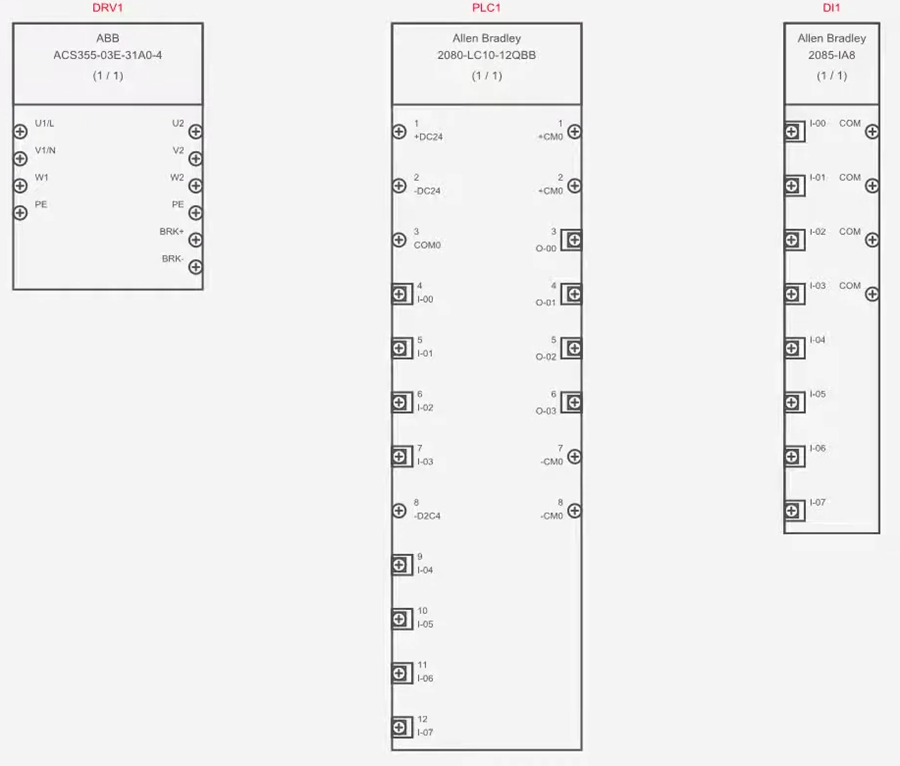
For example, the blocks below represent components of three different classes.
Each class’s template blocks have been modified to showcase how different widths and terminal spacings can be achieved directly by the block generator, instead of manually making those modifications after the blocks have been generated.
Customizing a template block
To customize a template block for class, go to the Block Generator tab, select Open template block, choose the desired class and click OK.
No terminals exist in the template blocks, since they are merely templates and have no actual terminals.
Before making any modifications, go to the Drawing tab and activate Show Grid and Snap to grid. This is important, since connection points (which terminals have) must be on the main grid.
To change the width, select the rectangle, then click and drag a construction point (indicated by a red circle at two of the corners of the rectangle) as needed.
To change spacing between terminals, expand the properties of the template block in the tree view and change the AutoCreation Channel Spacing properties. The value represents the number of grid steps between the terminals.
Once desired modifications are made, select the template block in the tree view, go to the Home tab and Save.
When prompted to save it to a folder in the symbol library, cancel out. The changes will be saved, but the template won’t be saved as a symbol in the symbol library, which wouldn’t make sense anyway.
Result
The block generator will use that template block when generating new blocks of components of that class. Existing blocks will be unaffected.
If you have an existing block for which you want the new template to apply, select the existing block, go to the Block Generator tab, select Open Component, then click Generate Block.
Related Tutorials
- Creating/modifying symbols and blocks (6:36)
- Block Generator (8:22)
- Adding Port Types (6:00)
- Drawing tools overview (9:31)