#1
Creating a System
Description
In this SkyCAD tutorial, you’re going to learn how to create a system.
Topics covered
System, Design-by-System, Creating a System, Unlinked OPR, Grouping, Virtual Location, Virtual Layout, Unassigned IO, Convert Project to System, Convert to System, Options, Configuration Management.
Main content
If you find yourself copying portions of designs from one project to another, this is a good indication that you would benefit from defining those commonly used portions of designs as systems, so you can use them again and again, without having to draw everything from scratch each time, or copying and pasting from old projects.
Design-by-Systems is a Pro feature, so it’s expected that you have some SkyCAD experience. If not, please view at least the Get Started tutorials, as well as the “Introduction To Systems” and “Using Systems in Projects” tutorials, if you haven’t done so already.
A good example of a system is something which you may use in several projects, though not necessarily in all projects.
A conveyor is a good example of this, as a project may have one conveyor, several conveyors or none at all.
A junction box is also a good example of a system for the same reasons.
Creating a system
To create a system, select SkyCAD in the tree view, go to the Create/Add tab and select New System.
From here on, design your system just as you would design a project.
You can expand the properties of the system in the tree view to change the name and other details, and you can add sheets, components, locations, do panel layouts, etc. just as you would for a project.
Although creating a system is very similar to creating a project, some aspects of a system can be left as ‘incomplete’; e.g.
- part numbers do not have to be assigned to each component, as you may only want to do that once the system is added to a project
- some OPRs may remain unlinked, until the system is added to a project and the system OPRs are linked to the project OPRs
As a matter of fact, Systems can not only have ‘incomplete’ information, but there are also some features specific to Systems detailed below.
Unlinked OPRs
When systems are added to projects, some of the wires may need to be linked to other wires in the project using OPRs.
If it is a large system with many such cases, it can be easy to forget to link some of those wires.
To reduce this risk, when creating your system, you can insert unlinked OPRs where wires will need to be linked to wires in the project.
To do this, insert the OPRs as usual, but hit ESCAPE before inserting the second OPR.
This will place an OPR arrow without a cross-reference displayed.
Then, once you add this system to a project, you can select the project in the tree view, go to the Show tab and select Unlinked OPRs to see all the OPRs which haven’t been linked to anything yet.
This is a good method to ensure you haven’t forgotten to link any wires.
Graphical Groupings
If you want a system’s schematics to be integrated directly into the project’s sheets, instead of the system having its own sheets, you can use groupings.
Select your system in the tree view, go to the Create/Add tab and select New graphical grouping.
These groupings behave like sheets.
You can rename groupings, and draw your schematics, just as if they were sheets.
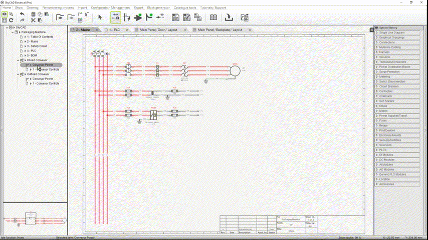
For example, below is a system with two groupings; one for power:

and one for control:

Components from different groupings can be linked together using Link With.
Of course, part numbers can be assigned to the components too.
In our case, we want this system to be used for a variety of conveyor sizes, so it would make sense to assign part numbers to the control equipment only, since those part numbers would not change based on the motor size.
Defining virtual location layouts
Following the conveyor system example above, let’s imagine that the conveyor does not have its own panel, but the components are added to a larger panel.
Once a system is added to a project, the components can be laid out in batches, instead of having to lay out each component one-by-one, every time we use that system in a project.
This makes doing your panel layout much faster.
In the example below, you can see how all the conveyor door-mounted components for both systems can be laid out on the larger panel (called Main Panel) all at once.

This is done by creating a virtual location in the system.
To create a virtual location such as this:
- Open the system by itself (not in the context of a project).
- Add a new location to the system via the Create/Add tab.
- Expand the properties of the location and check the Virtual Part property so that this location does not appear in any parts lists or BOMs, since it is not a real location.
- Following the example above, we might name this virtual location “Door”, since it is a virtual location for the door-mounted components.
- Add a layout block to the location via the Create/Add tab.
- Lay out your components in the virtual location layout (the components must be assigned to the location).
- Expand the properties of the layout block and de-select the Opaque Background property.
- The Width and Height properties of the layout block are not very important, but try set them to more-or-less represent the overall footprint of the components in the layout.
- You will most likely want to de-select the Draw Contour property, so the contour is not visible once this virtual location layout is laid out on a project’s location layout.
Once a system with virtual locations is added to a project, the system’s virtual location(s) must be assigned to the relevant project location(s).
Then, the virtual location layout can be laid out via Layout Element, under the Layout Tools tab.
Unassigned IO
Unassigned IO can be added to systems via the Create/Add tab, or imported from Excel.
This can be used to achieve schematic generation from an IO list, once the system is added to a project.
Converting a project to a system
If you have a project that you wish to convert to a system, you can select the project in the tree view, go to the Home tab and select Convert Project to System.
This will not affect the project, but simply create a copy of the project as a system.
If you only want to convert some parts of the project to a system, first convert the entire project to a system, then delete the extra sheets, symbols, locations, terminal strips, etc. that you don’t want, until you’re left with only what you want in the system.