
#1
Symbol Library, Catalogue & Other Fundamentals
Description
In this tutorial, you will learn the difference between the symbol library and the catalogue, as well as other fundamental concepts and relationships in SkyCAD’s architecture: classes, sub-classes, catalogue parts, catalogue, symbols, blocks, symbol library.
Understanding how these elements relate to each other will improve your experience.
Topics Covered
Classes, Symbols, Symbol Library, Catalogue parts, Catalogue, Blocks.
Main Content
Symbol:
A graphical object used to represent a component.
Symbols have no part number, manufacturer, layout image, etc.
When a symbol is inserted onto a sheet, a blank component is automatically created in the background and linked to the symbol.
Such blank components have generic connection port names (A1, A2, L1, +, etc.), which will be shown on the symbol, but these are usually only temporary, placeholder connection port names, which will be replaced if a catalogue part (see below) is assigned to the component.
Block:
A special kind of symbol created using the block generator.
The block generator allows you to create a catalogue part (see below) and blocks at the same time.
When a block is inserted onto a sheet, the catalogue part is automatically assigned to the component.
For creating catalogue parts with I/O (PLCs, PLC modules, drives, soft starters, etc.) use the block generator.
Symbol library:
A collection of folders which contain shortcuts to symbols and blocks.
During quick setup, you chose one of the following: IEEE, IEC and Aus/NZ.
That choice decided which symbol library, symbols, blocks, drawing orientation and numbering formats became the default in your environment.
In a symbol library, you can re-arrange, rename, add, move and delete folders as needed.
You can add more symbols and blocks by:
- modifying a similar symbol and doing a Save As (this tutorial shows how to create and modify symbols),
- creating a symbol from scratch by following the tutorial
or - creating a catalogue part and block at the same time using the block generator (for components with I/O)
Symbols and blocks can be copied/cut and pasted between folders.
How to change the active Symbol library.
Catalogue part:
A real-world component (usually purchased from a vendor) which has a part number, manufacturer, technical specifications, can have specific connection port names, layout images, price, etc. which is saved to your SkyCAD catalogue.
All that information (part number, etc.) is saved with the catalogue part, not with the symbol or block.
When you assign a catalogue part to a component, that catalogue part information is applied to the component.
Some of it will be displayed on any associated symbols/blocks, such as connection port names (A1, A2, L1, +, etc.).
Each catalogue part belongs to a SkyCAD class: circuit breaker, contactor, PLC, relay, connector, etc.
Catalogue parts are not always represented by symbols or blocks in your project: e.g. an end stop in a terminal strip can be assigned a catalogue part, but it will not be shown as a symbol on the schematics, though it may be shown in a panel layout.
Catalogue:
The catalogue refers to all the catalogue parts saved in your SkyCAD environment.
If you don't find the catalogue parts you're looking for, you can try find them in the online parts catalogue or add them to your catalogue yourself using the standard tools (for basic components) or the block generator (for more complex components; e.g. with I/O).
Class:
In SkyCAD, everything belongs to a class.
Classes can be thought of as “categories”.
Examples of classes are Circuit breaker, Relay, PLC, Sheet, Project, Revision, Graphical block, etc.
Each class has its own properties and settings, such as which numbering format is applied to that class, what properties it has (e.g. Voltage, Current, Quantity, etc.) and how they function, and more. To change how all objects of a certain class behave (e.g. Relay), edit that class.
How to create and modify a class.
Sub-class:
A child (sub-class) of a class.
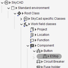
Above is an example of the class hierarchy.
The EStop class (selected) is a sub-class of the Button class, which is a sub-class of the Component class, which is a sub-class of Work field classes, which is a sub-class of Root Class.
A sub-class inherits all the properties, settings and behaviour of its parent class.
Workflow example:
To better understand the concepts, check the schematic in the image below, showing two motor starter circuits.
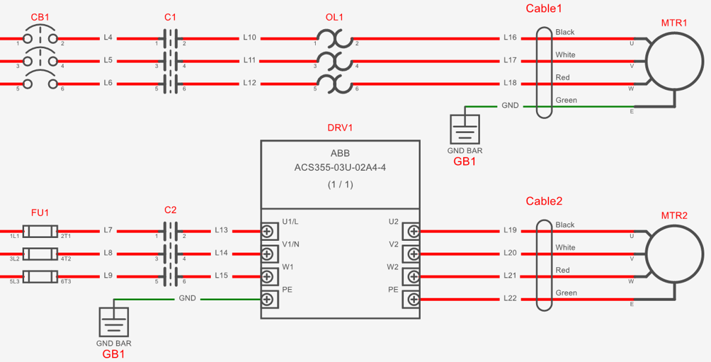
To draw these circuits, symbols and block were inserted from the Symbol library.
Notice the same contactor symbol is used for both circuits.
When added to the project, these contactors were named C1 and C2 respectively, due to the Root setting in the Contactor class settings and the numbering format used by the Contactor class.
The same numbering logic applies to all objects (cables, motors, drives, wires, etc.).
When the drive (DRV1) block, created with the block generator, was inserted onto the sheet, the catalogue part (ACS355-03U-02A4-4) was automatically assigned to the drive.
The other components do not have catalogue parts assigned to them yet.
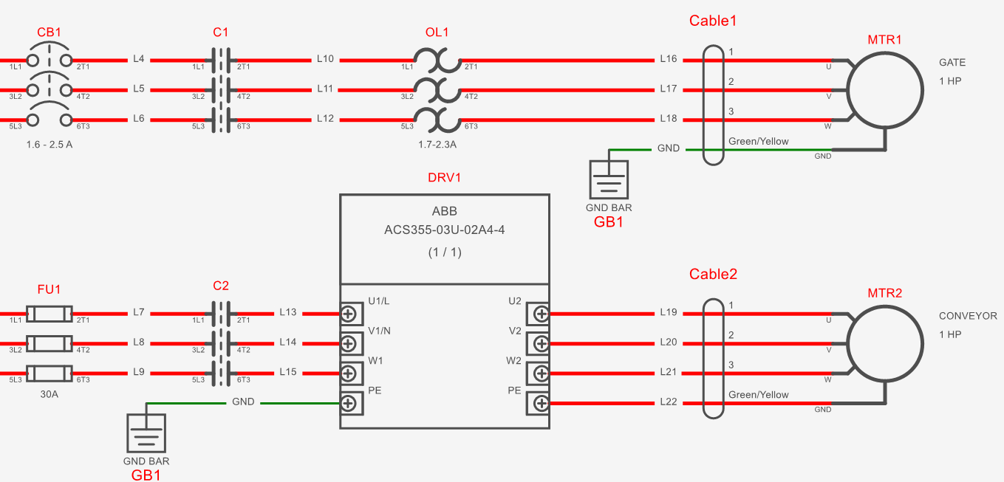
Once catalogue parts are assigned to all other components, the pin numbers may change, cable wire numbers/colors may change, and additional information (e.g. current, HP, etc.) may be displayed.
Related Tutorials
Catalogue tools (12:55)
Block generator (8:22)