#1
Component Connection Point Blocks
Description
In this tutorial, you’ll learn how to depict individual component connection ports using Component Connection Point Block symbols.
If you wish to depict individual component connection ports of terminals, kindly refer to the Terminal connection point blocks tutorial instead.
Topics covered
Component connection point block, port, terminal, pin.
Main content
If you want a small symbol to depict one particular connection port of a component, use the Component Connection Point Block symbol.
- Method 1 – Insert symbol, add component, assign catalogue part, choose port
- Method 2 – Component with assigned catalogue part already exists in the project. Insert symbol, choose port
- Method 3 – Copying and pasting the symbol, which may be useful for depicting busbar, ground bar and/or neutral bar connections
Method 1 – Insert symbol, add component, assign catalogue part, choose port
- Open the Terminals/Connectors library folder
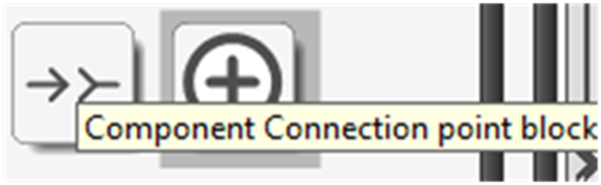
- Scroll to the bottom and select the Component Connection Point Block symbol

- Insert it on a sheet
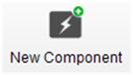
- Go to the Create/Add tab and select New Component
- Choose the class of component you want to add, then click OK
- Use Assign from Catalogue to assign a catalogue part to the newly added component
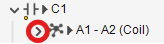
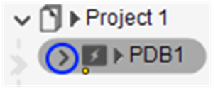
- Select the arrow to the left of the component to expand its list of connection ports

- If you need to add connection ports to the component, follow Method 3 or these steps:
- If you do not need the new connection port(s) to belong to connection port group(s), e.g. a group of internally bridged connection ports, coil, an NO or NC contact, etc.:
- Go to the Create/Add tab and select New Connection Port as many times as needed
- Right-click on the component and Save to avoid having to follow these steps in future
- If you need the new connection port(s) to belong to new connection port group(s):
- Go to the Create/Add tab and select New Connection Port Group
- With Connection port group selected, click OK
- Set the Flow Through (the net will flow through the connection port group) and Type properties if you wish
- Select the newly created connection port group, go to the Create/Add tab and select New Connection Port as many times as needed. To see the connection ports listed, click the arrow:
- Right-click on the component and Save to avoid having to follow these steps in future
- If you need the new connection port(s) to belong to existing connection port group(s):
- Close the dialog box
- Select the project in the tree view
- Go to the Show tab and select Components
- Select the component, go to the Create/Add tab and select New Connection Port as many times as needed
- Select the component, go to the Show tab and select Connection Port Groups while holding CTRL
- Click and drag the new connection port(s), one by one, onto the desired connection port group(s) while holding SHIFT
- Right-click on the component and Save to avoid having to follow these steps in future
- Follow Method 2 below
- If you do not need the new connection port(s) to belong to connection port group(s), e.g. a group of internally bridged connection ports, coil, an NO or NC contact, etc.:
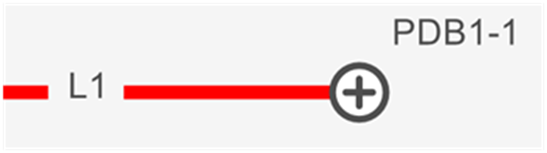
- Select the connection port you want the Component Connection Point Block to depict and click OK.
- The symbol is inserted and linked to the chosen connection port
Note: If you made a mistake and wish to link the symbol with a different connection port, select the inserted Component Connection Point Block symbol and select Link With from the Home tab.
Method 2 – Component with assigned catalogue part already exists in the project. Insert symbol, choose port
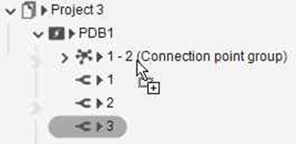
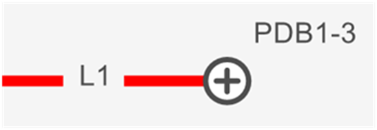
Before following the steps below, we inserted a power distribution block symbol onto a sheet and assigned a catalogue part to the component.
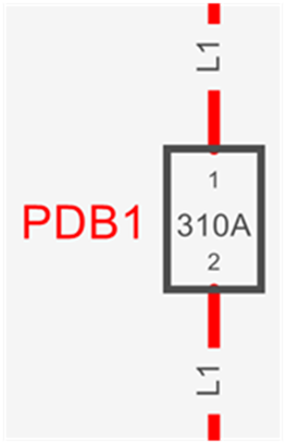
This power distribution block has more than just two connection ports, and many are not yet shown on the schematics.
Following the steps below, we depict a third connection port of PDB1 using the Component Connection Point Block symbol.
- Open the Terminals/Connectors library folder
- Scroll to the bottom and select the Component Connection Point Block symbol
- Insert it on a sheet
- Select the arrow to the left of the component to expand its list of connection ports
- If you need to add connection ports to the component, follow Method 3 or these steps:
- If you do not need the new connection port(s) to belong to connection port group(s), e.g. a group of internally bridged connection ports, coil, an NO or NC contact, etc.:
- Go to the Create/Add tab and select New Connection Port as many times as needed
- Right-click on the component and Save to avoid having to follow these steps in future
- If you need the new connection port(s) to belong to new connection port group(s):
- Go to the Create/Add tab and select New Connection Port Group
- With Connection port group selected, click OK
- Set the Flow Through (the net will flow through the connection port group) and Type properties if you wish
- Select the newly created connection port group, go to the Create/Add tab and select New Connection Port as many times as needed. To see the connection ports listed, click the arrow:
- Right-click on the component and Save to avoid having to follow these steps in future
- If you need the new connection port(s) to belong to existing connection port group(s):
- Close the dialog box
- Select the project in the tree view
- Go to the Show tab and select Components
- Select the component, go to the Create/Add tab and select New Connection Port as many times as needed
- Select the component, go to the Show tab and select Connection Port Groups while holding CTRL
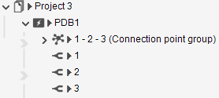
- Click and drag the new connection port(s), one by one, onto the desired connection port group(s) while holding SHIFT


- Right-click on the component and Save to avoid having to follow these steps in future
- Start Method 2 again from step 1
- If you do not need the new connection port(s) to belong to connection port group(s), e.g. a group of internally bridged connection ports, coil, an NO or NC contact, etc.:
- Select the connection port you want the Component Connection Point Block to depict and click OK.
- The symbol is inserted and linked to the chosen connection port
Note: If you made a mistake and wish to link the symbol with a different connection port, select the inserted Component Connection Point Block symbol and select Link With from the Home tab.
Method 3 – Copying and pasting the symbol, which may be useful for depicting busbar, ground bar and/or neutral bar connections
- Copy an inserted Component Connection Point Block symbol which represents a connection port (associated to the desired connection port group, if applicable) of the desired component
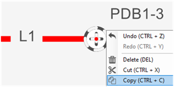
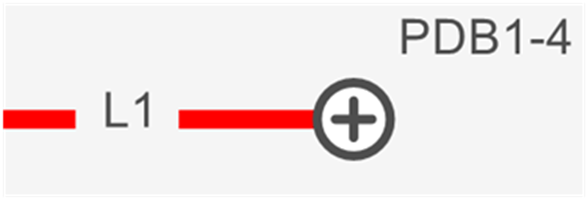
- Paste where desired. A new connection port of the component will be created, associated to the same connection port group (if applicable) as the copied symbol, and the new symbol will be linked to it
Note: If you made a mistake and wish to link the symbol with a different connection port, select the inserted Component Connection Point Block symbol and select Link With from the Home tab.
Note: When an inserted Component Connection Point Block symbol is deleted, the component is not deleted.