#1
Numbering process
Description
This tutorial explains how automatic numbering works for different items, such as projects, sheets, components and connections.
Topics covered
Sequential numbering, renumbering, renumber sheets, renumber wires, move connection text on axis, uniqueness control, best practices for wire numbering.
Video version

Related tutorials
- Inserting connections (2:42)
- Inserting symbols (2:09)
- Renumbering orientation (1:00)
- Catalogue tools (12:56)
- Customizing numbering (3:00)
- Creating a numbering format & assigning it to a class (2:00)
- Wire Lists and Single Wires (3:00)
- Harness features (17:46)
- Adding connectors to components (5:00)
Written Version
Objects are numbered automatically when created
In SkyCAD, projects, sheets and components are numbered automatically when created.
Component numbers are influenced by your choices during quick setup. For example,
if you chose IEC, motors will be M1, M2, and so on
if you didn’t choose IEC, motors will be MTR1, MTR2, and so on
if you chose rung numbering, motors will be numbered according to the rungs/lines on which the symbols exist
All nets, cables, wires1 and harnesses2 are numbered by going to the Renumbering Process tab and selecting Wire Renumbering/Processing.
1 Advanced license required
2 Pro license required
Customization
Numbering formats can be customized in many ways, such as including the sheet number or using rung/line numbers.
This is discussed further in the Customizing numbering tutorial.
Numbering formats can also be slightly modified by changing the Root property of the class - see the Catalogue Tools tutorial at 2:26.
(If you’re not sure how to achieve what you want, don’t hesitate to post on the forum.)
Manual numbering
To manually renumber an object as you wish, Explore the properties of the object and change the Tag/Number/Net property.
If you do that, the Tag Frozen property will automatically get checked, preventing automatic renumbering processes from renumbering it.
(Selecting a component/symbol, then Freeze ID from the Renumbering Process tab would also check Tag Frozen. Thaw ID would uncheck it.)
Uniqueness control
In SkyCAD, each object must have a unique number (unless you have the same numbers contained in several locations/panels in the same project, in which case see this forum thread).
If you manually renumber an object to a number which already exists, a message box appears: e.g.

Navigate to will display a dialogue box showing where the element is located, so you can choose if you want to change it or not.
Overwrite will force the number you defined and renumber the element which had that number originally.
Cancel cancels the process.
Automatic renumbering
Naturally, as your design evolves, objects will be moved, renamed, or deleted, thus causing the numbering of objects to not be sequential.
To renumber objects so their numbers are sequential, go to the Renumbering Process tab and select Sheet Renumbering, Wire Renumbering/Processing or Component Renumbering, depending on which types of objects you want renumbered.
Renumber All does all three processes but takes a little longer.
These commands apply throughout the entire project.
To renumber only a particular selection of objects, select them, then go to the Renumbering Process tab and select Renumber Selected Components or Selected Wire Renumbering/Processing, depending on which types of objects you want renumbered.
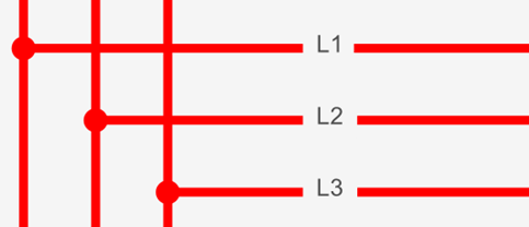
Numbering orientation
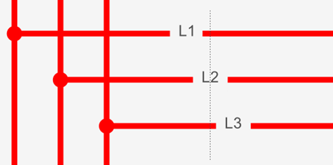
Automatic renumbering renumbers objects as they appear in the sheets, from top to bottom, left to right:

This can be changed by following the Renumbering Orientation tutorial.
Flag project as ‘Built’
If you’re modifying a panel, machine or harness that is already built and wired, you don’t want SkyCAD’s renumbering processes to change numbers in your design which already exist in the real world.
Go to the Renumbering Process tab and select Flag project as ‘Built’ so renumbering processes will not affect existing numbers.
Only new components, cables, nets, wires, harness branches, etc. that you add to the project will be affected by SkyCAD’s renumbering processes.
Show or hide connection number
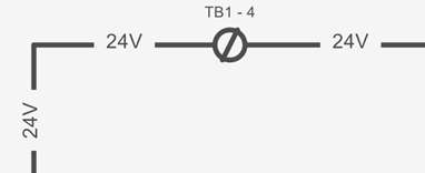
If you have a case where the connection numbers appear more often than you would like, e.g. 24V below:
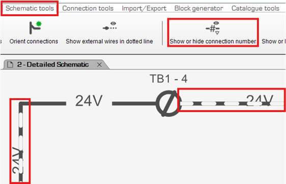
You can select the connection segments on which you do not want the numbers shown, go to the Schematic Tools tab and select Show or hide connection number:
Cable wiring information can also be hidden by selecting the connections associated to the cable, going to the Schematic Tools tab and select Show or hide cabling information:
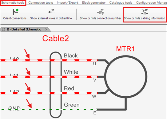
This will hide the Black, White, Red, Green text in the example above.
Move connection text on axis
If some connection texts are misaligned, go to the Schematic Tools tab and select Move connection text on axis.
Click once near the first connection and again near the last connection to form a perpendicular axis to the connections, represented by a thin, dotted line:
After that, the texts will be aligned along that axis:
Related tutorials
- Inserting connections (2:42)
- Inserting symbols (2:09)
- Renumbering orientation (1:00)
- Catalogue tools (12:56)
- Customizing numbering (3:00)
- Creating a numbering format & assigning it to a class (2:00)
- Wire Lists and Single Wires (3:00)
- Harness features (17:46)
- Adding connectors to components (5:00)