
Single Line Diagrams
#1
Single Line Diagrams
Description
In this tutorial, you will learn how to create a Single Line Diagram (SLD).
Topics Covered
Single line diagram, SLD, one line diagram, single line connections, link symbols, link cables
Main Content
What is a Single Line Diagram (SLD)?
An SLD is a high-level overview of the power distribution in a project.
The term “single line” means multi-phase wiring represented as a single line in the SLD.
An SLD is often a single page, whereas the detailed schematics consists of multiple pages.
The IEEE, IEC and Aus/NZ Example Project have SLDs on sheet 3.
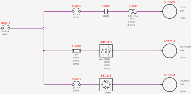
Example SLD
If you insert a component symbol (e.g. Overload) from the Single Line Diagram symbol library folder, you will notice no terminal numbers are displayed.
This is because an SLD provides a high-level overview only, not individual terminals.
An SLD component symbol typically represents a multi-pole device (e.g. 3-phase overload), without depicted each individual pole.
Similarly, the Single Line Connection - No Wire # symbol does not display net/wire number, because an SLD represents a multi-core cable and multiple-phase wiring using a single line only.
Because the symbols in the Single Line Diagram symbol library folder are designed specifically for SLDs, avoid using them for other purposes.
Drawing an SLD
Most of the symbols you would need to draw an SLD are located in the Single Line Diagram symbol library folder.
Inserting connections and symbols in an SLD is done in the same manner as other connections and symbols.
You can link symbols in the SLD with symbols in the detailed schematics.
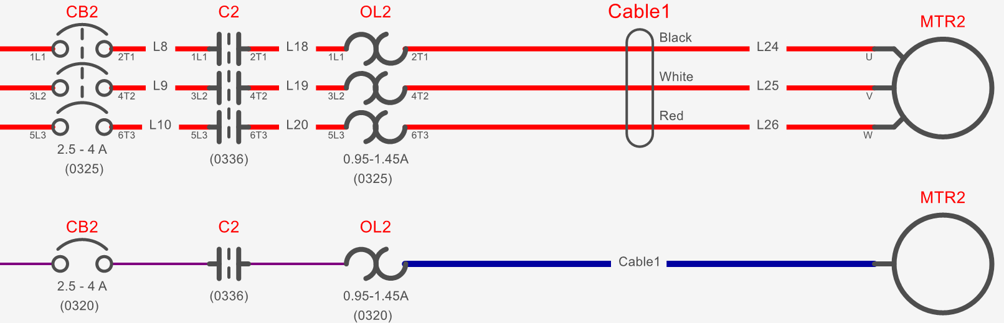
Linking cables in the detailed schematic with cables in the SLD
If you would like to show multicore cable names/tags on the SLD, there are two ways to do it:
1 - If the cable in the detailed schematic is represented by a cable indicator symbol
Insert a Cable Connection or Molded Cable Connection (whichever is appropriate) on the SLD
Run Wire renumbering/Processing from the Renumbering Process tab
Select the Cable indicator in the detailed schematic
Use Link With to link the Cable indicator in the detailed schematic to the (Molded) Cable connection in the SLD
Assign a catalogue part to the cable if applicable
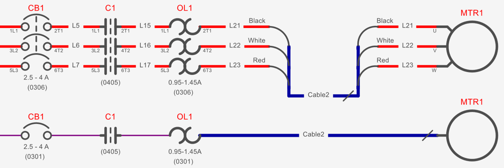
2 - If the cable in the detailed schematics is represented by a (molded) cable connection symbol:
Insert a Cable Connection or Molded Cable Connection (whichever is appropriate) on the SLD
Insert a Net info symbol from the Connections symbol library folder onto the cable connection in the SLD
Insert a Net info symbol onto the cable connection in the detailed schematic
Use Link With to link the two Net info symbols to each other
Run Wire renumbering/Processing from the Renumbering Process tab
Creating custom SLD symbols
If you would like to create custom SLD symbols, you can do it by following the Creating/modifying symbols and blocks tutorial, but you need to take an extra step once the symbol is properly saved into the Symbol library.
Right-click the symbol in the Symbol library and select Open block
Expand its properties in the tree view and check the Single line diagram block property
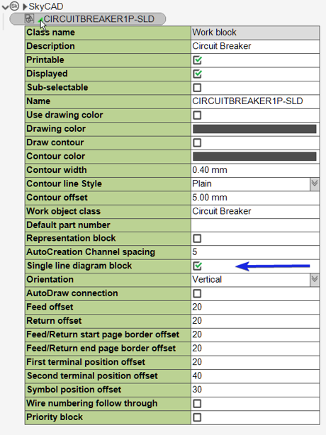
Right-click on the symbol in the tree view and choose Close, saving the changes when prompted