
Terminal strip layouts
#1
Terminal strip layouts
Description
This tutorial covers how to automatically generate terminal strip layouts within your schematics.
Topics covered
Terminal strip layout, terminal, fuse terminal, scaling.
Video version
NOTE: This tutorial video was created using an older version of SkyCAD.
Ribbon buttons' appearance and positions may differ if you're using version 1.3.25 or higher.
Thank you for your patience while we update this tutorial.
Related tutorials
- Introduction to terminal strips (6:57)
- Terminal strip management (11:44)
- Stacked terminals (3:35)
- Terminal connection point blocks (2:00)
Written Version
Introduction
If you have not done so already, please check the Introduction to terminal strips tutorial before continuing with this one.
If you need to show a graphical representation of the connectivity of a terminal strip, using the terminal strip layout is the best way to do that.
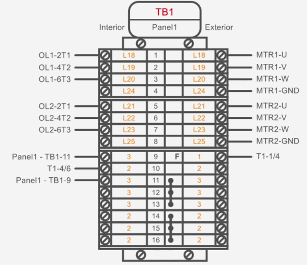
By default, a terminal strip layout shows:
Terminal strip name
Terminal strip location
Terminal strip description
- Terminal numbers (sequential by default, but can be overwritten by exploring the terminal strip properties, checking the Allow terminal numbering property, closing and re-opening the terminal strip view, then changing the values in the Name column)
Net numbers (orange text)
Connected elements (by default, Interior on the left and Exterior on the right)
Terminal bridges (terminals 11-13 and 14-16 are bridged in the image above; see this tutorial for how to add bridges)
Presence of fuses (represented by an “F”; see terminal 9 in the image above and this tutorial for how to add fuses)
End stops, separators, groups markers and other components
And more/less if customized (post on the forum and we will gladly assist)
Inserting a terminal strip layout
There are two ways to insert a terminal strip layout onto a sheet: from the tree view and from the terminal strip view.
From the tree view
Select the project in the tree view, go to Show tab and select Terminal Strips
Select the desired terminal strip, go to Terminal strip tools tab and select Lay out terminal strip
Select the sheet where you want to insert the layout and click OK
Insert the terminal strip layout onto the sheet
From the terminal strip view (Single level view or Stacked terminal view)
Reach the terminal strip (one way is to double-click any terminal symbol which represents a terminal junction in that terminal strip
Go to Terminal strip tools tab and select Lay out terminal strip
Select the sheet where you want to insert the layout and click OK
Insert the terminal strip layout onto the sheet
Modifying the terminal strip layout
Selecting the terminal strip layout on the sheet allows the operations below.
Change the size/rotation of the layout
Select the terminal strip layout and go to the Drawing tab
Select Scale with mouse scroll or Specify scale factor toscale the layout
and/orRotate 90 left or Rotate 90 right to rotate the layout
Split the layout
Select the layout and go to the Terminal strip tools tab
Select Split Terminal Strip Layout View
Select the desired position of the second half of the terminal strip layout
If one of the splits is deleted, the remaining layout becomes the full layout again.
Open terminal strip view
Double-clicking on a terminal strip layout will open the terminal strip view (Single level view or Stacked terminal view).
Show (N/C) for “Not Connected”
By default, terminal strip layouts will show a blank space beside a terminal junction not wired to anything.
If you prefer (N/C) to be displayed instead of nothing, select the terminal strip layout on the sheet, go to the Terminal strip tools tab and select Show ‘(N/C)’ for not connected.
Hide unresolved connectivity information
By default, unresolved terminal junction connectivity, if any, is displayed on the terminal strip layout as (TBD) for “To Be Defined” or connectivity information in parentheses.
As examples, see the red and blue rectangles in the image below.
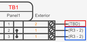
If you prefer to hide such unresolved connectivity information, select the terminal strip layout on the sheet, go to the Terminal Strip Tools tab and de-select Show unresolved connectivity info.
See the Terminal Strip Management tutorial to learn how to properly handle unresolved connectivity information, which is preferred to simply hiding that information.
Overwriting the orange text
By default, the orange text represents the net number that the terminal junction is connected to.
If you prefer to instead show a custom, manually-entered text, you can write the desired text in the Label Exterior Side (Side A) and Label Interior Side (Side B) columns, which are present in the terminal strip views (Single level view and Stacked terminal view).
If you cannot find those columns, you may have to unhide them by following this tutorial, starting at 0:35.
Note: by changing the label this way, it is not changing the net number, only the orange text.
Flip terminal strip layout
It is possible to flip the right and left sides of the terminal strip layout by selecting the terminal strip layout, going to the Terminal strip tools tab and selecting Flip terminal strip.
List block (table)
A useful alternative or supplement to a terminal strip layout is a list block.
This can be used to show information not shown in the terminal strip layout, such as the part number and manufacturer of the elements in the terminal strip.
To insert a list block:
Open the terminal strip view (Single level view or Stacked terminal view)
Go to the Home tab and select Insert List Block
Select the sheet you want the list block on and click OK
Insert the list block onto the sheet
More about list blocks in this tutorial at 1:05.
Adding other types of components to terminal strips
Terminal strips can contain other types of components, such as circuit breakers, relays, etc.
This can be useful for panel layouts where you want such components to be in the terminal strip panel layout view.
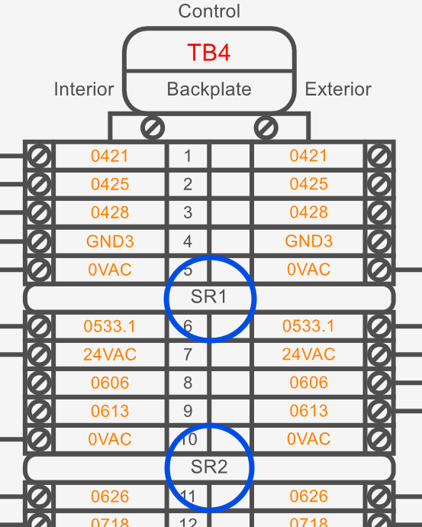
For example, below are four safety relays contained within a single terminal strip.
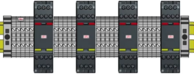
To add such components to a terminal strip:
Select the project in the tree view, go to Show tab and select Components
While holding Ctrl, select Terminal Strips from the Show tab. This will list both components and terminal strips in the tree view
Select the component(s) in the tree view you want to add to the terminal strip, go to the Home tab and select Cut
Select the terminal strip you want the component(s) to belong to, go to the Home tab and select Paste
Select the terminal strip, go to Show tab and select Terminal strip elements
Click and drag the component(s) within the terminal strip to where you want them to appear in the terminal strip panel layout view
When you insert the terminal strip into a panel layout, those component views will be included, if those components have layout views.
In terminal strip layouts, such components will appear as simple rectangles (see SR1 and SR2 circled in blue below).
To modify the default appearance of all components in terminal strip layouts
Open the file: "\SkyCAD Environments\Standard Environment\Catalogue\root class\SkyCad specific Classes\Graphical Element\graphical object\graphical block\List item\Component list item"
Modify the graphics as desired
- Be sure that the insertion point (depicted as a small, black cross) remains at the top middle of the graphic. (Insertion points can be reset by going to the Drawing tab, selecting Reset insertion point and clicking to define the insertion point.)
Go to the Drawing tab and select Show empty attribute names so you can see [Attribute 1]. This text attribute displays the name of the component. Move it to a new position if you wish.
Once done, close and save Component list item. When asked in which symbol library folder to save it, select Cancel.
Close and re-open SkyCAD
To modify the default appearance of how a specific catalogue part looks in terminal strip layouts
Open this file in SkyCAD:
"\SkyCAD Environments\Standard Environment\Catalogue\root class\SkyCad specific Classes\Graphical Element\graphical object\graphical block\List item\Component list item.SkyCadFile"Apply a Save As to Component list item. When asked in which symbol library folder to save it, select Cancel.
When prompted to name the file, for your own reference, name it similar to, but not the same, as the part number of the catalogue part you want this new graphic to apply to
Modify the graphics as desired
Be sure that the insertion point (depicted as a small, black cross) remains at the top middle of the graphic. (Insertion points can be reset by going to the Drawing tab, selecting Reset insertion point and clicking to define the insertion point.)
Move [Attribute 1] it to a new position if you wish.
Right-click on the file (now named similar to the part number of the desired catalogue part) in the tree view and choose Copy
Go to the Catalogue Tools tab, select Open Catalogue Part and follow the prompts to open the desired catalogue part
Right-click on the catalogue part in the tree view and choose Paste
To confirm it was done correctly, select the catalogue part in the tree view, go to the Show tab and select List item block. You should see your new file listed below
Close and save the catalogue part
Close and re-open your project to see the difference, assuming you already had that component in a terminal strip layout
Related tutorials
Terminal strip management (11:44)
Stacked terminals (3:35)
Adding fuses to fuse holders (1:00)