
Introduction to terminal strips
#1
Introduction to terminal strips
Description
This tutorial is an introduction to how terminals work.
Topics covered
Terminal, Terminal strip, terminal junction, insert symbol on axis, flow through, terminal strip view.
Main content
Thank you for your patience while we update this tutorial.
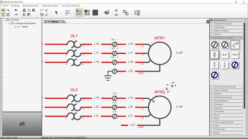
Related tutorials
- Terminal strip layout (6:00)
- Terminal strip management (11:44)
- Stacked terminals (3:35)
- Terminal connection point blocks (2:00)
Written version
Introduction
Hierarchy
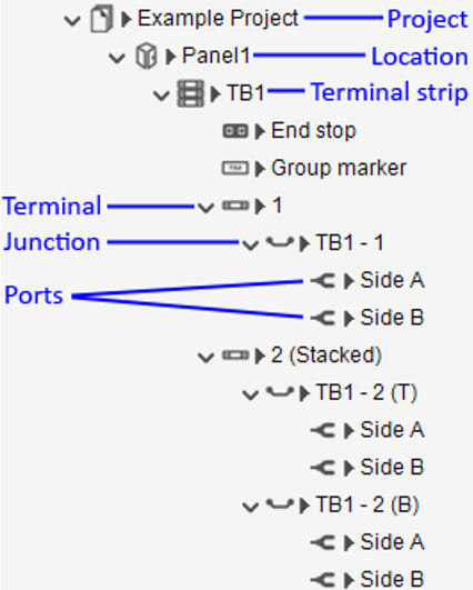
The image below shows how terminals are structured in SkyCAD.
Terminology
- Location: Most commonly a panel/enclosure, but can also be a building, room or area. See Managing panels/cabinets/locations for more information.
- Terminal strip: Contains multiple terminals, end stops, group markers, separators, etc. A terminal strip must belong to a location. There may be several terminal strips in a project. By default, terminal strips are numbered TB# (if using IEEE or Aus/NZ) or X# (if using IEC).
- Terminal: The item you buy from the manufacturer. It is the entire object shown in the image above. A terminal has at least one junction, which has connection ports. By default, terminals are numbered sequentially, starting from 1.
- Junction: A set/level of connection ports. Every terminal has at least one junction. In the image below of a 2-tier stacked terminal, there are two junctions circled in red: top level and bottom level. Each junction has two connection ports.
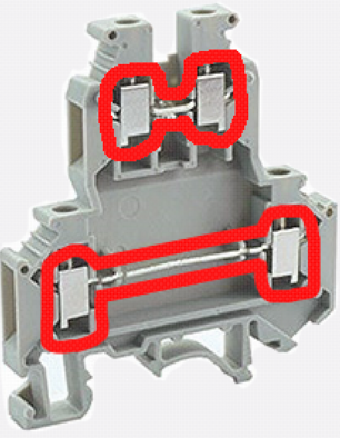
- Connection port: A place where a wire physically connects to the terminal, by using a screw, spring clamp, etc.. Every terminal has at least two connection ports.
Inserting terminal symbols
There are several symbols in the Terminals symbol library folder, but these two symbols look the same:
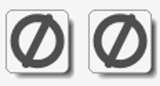
If you hover the mouse cursor over each of them, you will notice they have different descriptions.
The first symbol displays the terminal strip name, followed by the terminal number and level (if it is a stacked terminal).
The second symbol displays the net number(s) connected to it.
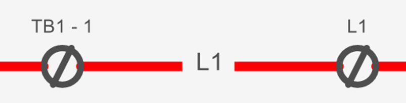
Both symbols, as well as the fuse terminal symbol, represent one entire junction (two connection ports).
(If you would prefer to use a symbol which represents half of the junction [one connection port], use terminal connection point blocks instead.)
Adding any of these “junction” terminal symbols to a sheet for the first time in a project automatically adds a location to the project, if one doesn’t yet exist, adds a terminal strip to that location, if one doesn’t yet exist, adds a terminal to it, adds a junction to it and links the symbol to the junction.
After that, the next time you insert a terminal symbol, a terminal will be added to the last-used terminal strip, and the symbol will be linked to a junction of that new terminal.
To use a different terminal strip instead, hold SHIFT when inserting the symbol.
(All terminal symbols behave in this manner, except for terminal connection point block symbols.)
To move terminals from one terminal strip to another, select them, go to the Terminal Strip Tools tab and select Assign to terminal strip.
Select the desired terminal strip and click OK.
Multiple terminal symbols can be inserted very quickly by double-clicking the symbol from the library or by using Insert symbols on axis, both explained in the Inserting Symbols tutorial at 0:50.
Flow Through (same net on both sides of the terminal junction)
In SkyCAD, the term “Flow Through” means to allow the net on both sides of a symbol to be the same.
Notice terminals TB1-1 and TB1-2 below.
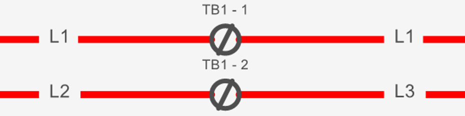
TB1-1 has its Flow Through property checked, meaning that the net, L1, flows through the terminal junction.
TB1-2 has its Flow Through property unchecked, meaning that the net, L2, does not flow through the terminal junction, and thus a new net, L3, is created on the opposite side.
By default, these terminal symbols have their Flow Through properties checked.
To change that:
- Right-click on the symbol and choose Open Block
- Select the symbol in the tree view, go to Show tab and select Connection point group
- Expand the properties of Junction and uncheck the Flow Through property
- Close and save the symbol
Closing and re-opening the project will reload such symbols used in the project.
Then, run Wire/Renumbering Processing from the Renumbering Process tab to affect the net changes.
Terminal strip view
To finalize terminal connectivity, check the terminal strip view, known as Single level view for single level terminal strips and Stacked terminal view for stacked terminal strips.
A terminal strip view is a comprehensive view of everything related to that terminal strip: terminals, accessories, connectivity, terminal strip properties, etc.
There are two ways to open a terminal strip view:
- Double-click any terminal symbol which represents a terminal in that terminal strip
- Select the project in the tree view, go to Show tab, select Terminal Strips and double-click the desired terminal strip
Properties
When you open a terminal strip view which contains stacked terminals, the stacked terminal view will be displayed by default.
When you open a terminal strip view which does not contain stacked terminals, the single level view will be displayed by default.
You can explore the Terminal strip properties by double-clicking the terminal strip name or by selecting the triangle (circled in red below) beside the name.

Here are some terminal strip properties and their uses:
Description: Can be used to describe the purpose of the terminal strip, e.g. Control, Power, 24VDC, etc.
Name: The name automatically designated to the terminal strip by the numbering format assigned to terminal strips. Change the name if desired.
Side A label: Set to Exterior by default, thus there is a Connected Exterior side column in the terminal strip view. Change it to Left, Right, Top, Bottom, etc. if desired. If there is no concept of exterior/interior for your terminal strip (e.g. it is a power distribution terminal strip), turn off Filter by locations too (see below).
Side B label: Set to Interior by default, thus there is a Connected Interior side column in the terminal strip view. Change it to Left, Right, Top, Bottom, etc. if desired. If there is no concept of exterior/interior for your terminal strip (e.g. it is a power distribution terminal strip), turn off Filter by locations too (see below).
Invert sides: Flips the Connected Side A/B (Exterior/Interior) sides in the terminal strip view and terminal strip layout. This checkbox is also toggled by selecting the terminal strip, going to the Terminal Strip Tools tab and selecting Flip terminal strip.
Location in: The location of the terminal strip. Ensure this is accurate before defining the connectivity, as changing the location later can affect connectivity.
Tag frozen: If this is checked, automatic renumbering processes will not change the Name of this terminal strip.
Filter by locations: Allows SkyCAD to automatically connect components on the correct side (Exterior/Interior) of the terminal based on what locations the components are assigned to. If a component is located in the same location as the terminal strip, it gets connected to the Connected Interior Side. If a component is located in a different location than the terminal strip, it gets connected to the Connected Exterior Side. If there is no concept of exterior/interior for your terminal strip (e.g. it is a power distribution terminal strip), turn off Filter by locations. In which case, you may also wish to change the Side A/B label property values mentioned above.
Show unresolved connectivity info: Unchecking this box will hide any (TBD) values (To Be Defined) in the connectivity table and terminal strip layout. Normally, it is better to keep this checked and resolve (TBD) values following this tutorial.
Show ‘(N/C)’ for not connected: Checking this box will display (N/C) instead of empty values in the connectivity table and terminal strip layout.
Allow terminal numbering: Check this box, then close and re-open the terminal strip to reveal the Name column, allowing you to name the terminals manually.
Levels labels: Only applicable to stacked terminals. By default, this property is set to ‘T,M,B’ for Top, Middle, Bottom, resulting in the top level of a 2-level terminal being referenced as ‘T’ and the bottom level as ‘B’. Change this property’s value, separating the terms by commas, to change how the levels are labeled.
Prefix terminal location path on connectivity info: Only applicable when two terminals of different terminal strips are connected together.
Unchecking this property will hide the location of this terminal wherever it is referenced in other terminal strips.
For example, in the image below, the property is unchecked in TB1, but checked in TB2. Thus, when TB1-1 is referenced in TB2, the location of TB1-1 is not mentioned.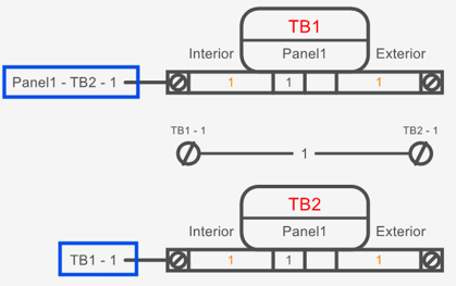
Columns
The terminal strip view contains a connectivity table. Some columns in that table are:
Connected Side A/B (Exterior/Interior) side: Elements connected to the terminal junction. Results may be affected by the Filter by locations property mentioned above. These columns can be renamed by changing the Side A Label and Side B Label properties mentioned above.
Bdg: Internal/Mechanical bridges/jumpers between terminal junctions. See the Terminal strip management tutorial for more information on bridging. Bridges can be graphically represented on schematics using the Terminal Bridge/Jumper symbol in the Terminals symbol library folder, or by inserting a terminal strip layout.
Net number: The net number(s) connected to the terminal junction. If the terminal junction is not Flow through (see above) then two net numbers could be shown.
Net type: The class of net (Power, Control, etc.) connected to the terminal junction.
Columns can be moved, hidden and unhidden by selecting a column heading, going to the Home tab and selecting Show hidden columns, Hide column, Move column left or Move column right.
Items (terminals, separators, end stops, etc.) can be re-arranged by clicking and dragging.
Navigation
Any item in the terminal strip view (terminal, separator, end stop, etc.) can be selected and navigated to by right-clicking on it and choosing Navigate.
Accessories
Accessories can be added to the terminal strip by selecting the terminal strip and going to the Create/Add tab.
Similarly, accessories can be added to terminals by selecting the terminal and going to the Create/Add tab.
Related tutorials
- Terminal strip layout (6:00)
- Terminal strip management (11:44)
- Stacked terminals (3:35)
- Terminal connection point blocks (2:00)