#1
Block Generator
Description
This tutorial covers how to use the Block Generator in order to let SkyCAD automatically generate symbols and blocks based on part specifications. This is especially useful for components such as PLCs, PLC Modules and Drives.
Topics Covered
PLC, PLC modules, drive, soft-starter, IO, input channel, output channel, analog input channel, analog output channel, digital input channel, digital output channel, relay output, digital output module, digital input module, analog input module, analog output module, symbols, blocks, terminal name, terminal label.
Video Version

Related Tutorials
- Customising the block generator (6:20)
- Multi-terminal channels & internally bridged terminals (2:00)
- Moving terminals across the block (1:00)
- Changing channel types (2:00)
- Adding Port Types (6:00)
- Adding channels to block (1:00)
- Adding connectors to components (5:00)
- Example drive (6:44)
- Linking symbols together (2:38)
- Using PLCs (7:21)
- Showing component properties around a symbol (2:25)
- Pin-out blocks/attributes (3:00)
Written Version
Introduction
Many of the symbols you'll need in your schematics are quite basic, such as circuit breakers, normally open contacts, coils, lights, buttons, etc.
Using the steps shown in the Creating/modifying symbols and blocks tutorial is perfect for making symbols like these.
For creating components with I/O (PLCs, PLC modules, drives, soft starters, etc.) use the block generator instead.
The block generator allows you to simply create a component, specify its terminals, and let SkyCAD generate the block(s) for it.
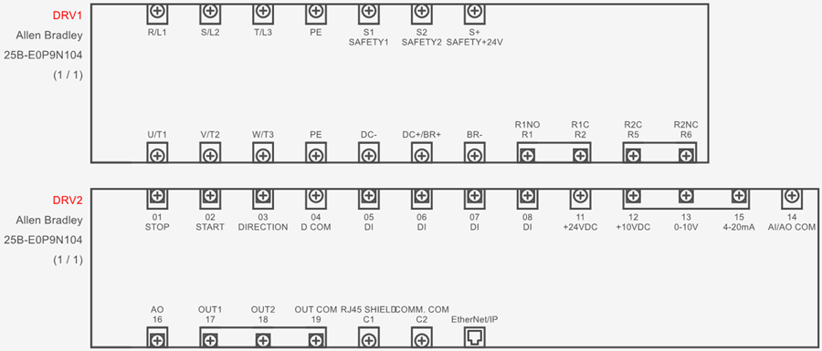
Here is an example of two blocks linked together to represent a single drive (IEEE or Aus/NZ setup):

Here is an example of two blocks linked together to represent a single drive (IEC setup):
You can split up such blocks into several smaller blocks if you wish.
Many customizations can be applied to these blocks, such as moving/rotating the terminals, changing the look of the terminals from screw terminals to other types, grouping terminals together, etc.
Creating a component and block
To create a component with the block generator:
Go to the Block generator tab and select Add new component
Choose the class of component and click OK (if the desired class doesn’t exist, create it by following the Catalogue Tools tutorial)
Enter the part number of the component and click OK
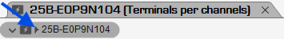
Optional: Click the triangle beside the part number to explore the properties of the component to define optional properties (Description, Manufacturer, Image, etc.)
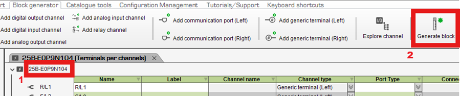
Add all the component’s channels/ports/terminals/commons using those specific buttons in the Block generator tab
From the Block generator tab select Generate block and follow the prompts
Explanation of channels/ports/terminals/commons
Add ______ channel buttons should be used for a component’s IO to ensure IO lists are correct and other IO-related features work properly.
If you wish to add multiple terminals to the same IO channel, follow the Multi-terminal channels & internally bridged terminals tutorial.
If a component has a programmable IO channel (e.g. it can be either DI or DO), simply add that channel as the one which you guess will be used most frequently (either DI or DO).
Whenever you add that component to a project, you’ll easily be able to change it by following “Part 2” of the Changing channel types tutorial.
Once the block is generated, inputs channels will be on the right (if using IEEE or Aus/NZ) or top (if using IEC) of the generated block, and output channels will be on the left (if using IEEE or Aus/NZ) or bottom (if using IEC) of the generated block.
These can be moved by following the Moving terminals across the block tutorial.
Add communication port can be used for any type of communication port, such as RJ45, DB9, USB, HDMI, etc.
Add generic terminal should only be used for terminals which are neither IO terminals nor communication ports.
Examples of this would be power terminals, shield terminals or any other miscellaneous terminals.
If you wish to add multiple generic terminals which are internally bridged together, follow the Multi-terminal channels & internally bridged terminals tutorial.
Add ______ common are only available for PLC modules and can be used to take advantage of the Insert Commons feature which saves users a little time by automatically adding commons to the sheet, as described in the Using PLCs tutorial at 6:10.
Once the block is generated, feed commons will be on the right (if using IEEE or Aus/NZ) or top (if using IEC) of the generated block, and return commons will be on the left (if using IEEE or Aus/NZ) or bottom (if using IEC) of the generated block.
These can be moved by following the Moving terminals across the block tutorial.
If you make a mistake and would like to change the type of terminal you’ve already defined, follow “Part 1” of the Changing channel types tutorial.
Explanation of columns
Once you’ve added at least one channel, port, terminal or port to the component in the block generator, it will be added to the list and the following columns may be displayed:
Name: Mandatory. Enter the terminal/port name/number as it appears on the component. For example, in the drive example above, the first terminal’s Name would be R/L1.
Label: Some components have names/numbers as well as secondary labels for some terminals/ports.
In the drive example above, the first terminal of the first block is named R/L1 and doesn’t have a secondary label.
However, the first terminal of the second block is named 01 and has a secondary label of STOP (these are physically printed near the terminal on the drive), thus the Name should be 01 and the Label should be STOP.
In summary, if a terminal/port has a label, enter it in the Label property as it appears on the component.
Channel name: Only applies to IO channels. If two terminals have the same channel name, then they belong to the same channel. The cells is this column are read-only.
Channel type: Indicates the type of channel/port/terminal/common. The cells is this column are read-only.
Port Type: Indicates what the appearance of the channel/port/terminal/common will be once the block is generated. Choose the desired appearance from the drop-down menu.
Connector: Indicates to which connector, if any, the port/terminal/common is assigned. To assign ports/terminals/commons to a connector, select them holding SHIFT (to select a range) or CTRL (to select individually), then select Assign to connector from the Block Generator tab.
A dialog box will be displayed, where you can select to which connector of the component you want those terminals assigned.
If you don't have any connectors added yet, go to the Create/Add tab and select New Connector.
Expand the properties of the connector to check Virtual Part (so it doesn’t appear in parts lists) and define the Tag if you wish.
Select the connector and click OK to assign the ports/terminals/commons to that terminal.
(To see the terminal structure of the above example drive in the block generator, go to the Block Generator tab, select Open Component, select Drive, click OK, select 25B-E0P9N104 and click Open. You could also review the Example Drive tutorial.)
Generate block
Once you’ve fully defined the component in the block generator (except for the panel layout view), the final step is to let SkyCAD generate the graphical block(s) for the component.
All terminals in one large block
If you want one large block which includes all the terminals, select the component heading and click Generate Block from the Block Generator tab.
SkyCAD will ask you to enter a name for the block.
You will likely want to keep the name the same as the part number and click OK.
Follow the prompts to save it to any symbol library folder.
It is now ready to insert onto your schematics.
If you’d like to edit the part in the block generator, but have closed the part already, select the block, either on the schematics or in the symbol library, go to the Block Generator tab and select Open Component, or go to the Block Generator tab, select Open Component and follow the prompts.
Customizing the physical appearance of the block can be done as described in the “Modifying blocks” section below.
Terminals spread over several smaller blocks
Instead of (or in addition to) one large block which contains all the terminals, you could create several smaller blocks: e.g. one block with the power terminals and another with the control terminals.
To generate a block which includes only certain terminals, select those terminals using CTRL or SHIFT, then click Generate block.
When prompted to enter a name for the block, you may want to suffix the name with a descriptor about that block: e.g. <part number><type of terminals contained therein>.
If you insert several different blocks (e.g. one for power and another for control) but would like them to represent the same component, link them together.
Before linking them together ensure that no terminal is shown on more than one block, since any given terminal can only be shown once in a project.
Modifying blocks
Terminals can be clicked and dragged to move them around.
Clicking and dragging the last terminal on a block will automatically resize the block.
If you always want the distances between terminals to be different to the default distances, follow the Customizing the block generator tutorial.
Terminals can be moved to the opposite side of the block by following the Moving terminals across the block tutorial.
If you’d like to add terminals to an existing block that you’ve made, see the Adding channels to block tutorial.
If you’ve made changes to a block and would like those changes saved to the block in the symbol library, select the block, go to the Home tab and click Save.
Choose Yes when asked if you’d like to overwrite the file.
Related Tutorials
- Customising the block generator (6:20)
- Multi-terminal channels & internally bridged terminals (2:00)
- Moving terminals across the block (1:00)
- Changing channel types (2:00)
- Adding Port Types (6:00)
- Adding channels to block (1:00)
- Adding connectors to components (5:00)
- Example drive (6:44)
- Linking symbols together (2:38)
- Using PLCs (7:21)
- Showing component properties around a symbol (2:25)
- Pin-out blocks/attributes (3:00)