
#1
Terminal strip management
Description
This tutorial covers how to organise terminals within your terminal strips, such as sorting and moving terminals around, bridging terminals, and adding terminal strip accessories, like end stops and separators.
Topics covered
Terminal, separator, end stop, moving terminals sorting terminals, connect, disconnect, bridges, bridging.
Video version
NOTE: This tutorial video was created using an older version of SkyCAD.
Ribbon buttons' appearance and positions may differ if you're using version 1.3.25 or higher; e.g. Wire Number column renamed to Net Number, and Wire Type column renamed to Net Type.
Thank you for your patience while we update this tutorial.

Related tutorials
- Introduction to terminal strips (6:57)
- Terminal strip layout (6:00)
- Stacked terminals (3:35)
- Terminal connection point blocks (2:00)
- Numbering process (6:30)
Written Version
Introduction
If you wish to have accurate wire lists (Advanced/Pro license required) or terminal strip layouts in your project documentation, it is important to follow this tutorial to properly define terminal connectivity (what the terminals are connected to).
If you have not seen the Introduction to terminal strips tutorial yet, please view that before continuing with this tutorial.
Defining terminal connectivity is done in the terminal strip view (Single level view or Stacked terminal view) using the commands in the Terminal Strip Tools tab.
Terminal strip view
“Terminal strip view” is an umbrella term for “Stacked terminal view” and “Single level view”.
To open the terminal strip view, double-click any of the following objects related to that terminal strip:
- Terminal symbol on the schematics
- Terminal strip in the tree view
- Terminal strip layout
- Terminal strip list block
From the terminal strip view, you can explore the properties of the terminal strip by selecting the triangle (circled in red below) beside the name.

These properties are discussed in the Properties section of the written version of the Introduction to terminal strips tutorial.
Single level view
If the terminal strip does not have any stacked terminals in it, opening the terminal strip view will open the Single level view.
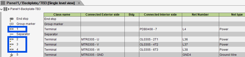
The blue rectangles above represent terminals.
Stacked terminal view
If the terminal strip has any stacked terminals in it, opening the terminal strip view will open the Stacked terminal view.
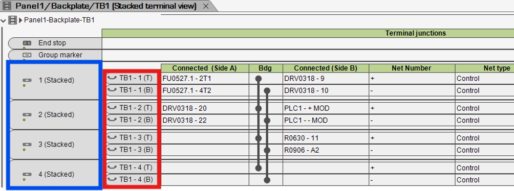
The blue rectangle above represents terminals.
The red rectangle above represents terminal junctions/levels. (T for top, B for bottom).
Navigation
From the terminal strip view, you can right-click any terminal or connected element and choose Navigate to navigate to it.
If you would like to see the terminal strip view and schematics at the same time, open the terminal strip view, go to the Home tab and select Send to Explorer view to open the terminal strip view in a separate window, allowing you to move it beside your schematics or to a different screen.
If you do this and select a terminal in the terminal strip view, the terminal junction symbol on the schematics will be highlighted, if that sheet if displayed.
The preview pane in the bottom-left corner of the screen will also show where the selected item appears on the schematics.
You can zoom and pan within the preview pane.
If a terminal has its Image property defined, the preview area will show the image instead of the symbol on the schematics. In such cases, to see where the symbol is on the schematics, select the Connected Exterior side (Side A) or Connected Interior side (Side B) element.
Accessories
Accessories, such as group markers, separators and end stops, can be added to the terminal strip via the Create/Add tab.
Sort/group/move/renumber terminals
Sorting terminals
In the Terminal strip tools tab are several tools to sort the terminals.
If the terminals are numerically and sequentially numbered (TB1-1, TB1-2, TB1-3, etc.), sorting terminals may change their numbers.
Sort based on wire number: Sorts terminals based on the Net Number column.
The sorting priority is as follows: empty, numbers, characters, letters.
Sort based on (Side A) elements (only available in Single Level View): Sorts terminals based on the Connected (Side A) side column.
The sorting priority is as follows: empty, numbers, characters, letters.
Sort based on (Side B) elements (only available in Single Level View): Sorts terminals based on the Connected (Side B) side column.
The sorting priority is as follows: empty, numbers, characters, letters.
If the terminal strip is selected when performing any of these actions, the sorting will apply to all the terminals in that terminal strip.
If certain terminals are selected when performing any of these actions, the sorting will only apply to the selected terminals.
Move/Group/Renumber terminals
Below are several methods to manually move/group/renumber terminals.
If the terminals are numerically and sequentially numbered (TB1-1, TB1-2, TB1-3, etc.), moving/grouping terminals may change their numbers.
Click and drag: Simply click and drag the terminals within the list to the desired positions.
Group terminals: Select several terminals (hold CTRL or SHIFT + click) you want grouped together, go to the Terminal strip tools tab and select Group terminals.
Move to position: Select the terminal you want moved, go to the Terminal strip tools tab, select Move to position, enter the desired position and click OK.
Assign to terminal strip: To move a terminal to a different terminal strip, select the terminal, go to the Terminal strip tools tab, select Assign to terminal strip, select the terminal strip you want the terminal moved to and click OK.
Allow terminal numbering: To number/name terminals manually, expand the properties of the terminal strip, check the Allow terminal numbering property, then close and re-open the terminal strip to reveal the Name column.
Enter values in the Name column to name the terminals manually.
Prepare to define connectivity
Defining connectivity is required if you want to have accurate wire lists (Advanced/Pro license required) or terminal strip layouts in your project documentation.
Defining connectivity means defining the values in the Connected Side A side, Bdg (bridge) and Connected Side B side columns in the terminal strip view.
Before doing that, follow the steps below in the order they are listed, or you may have to redefine some connectivity later.
- Complete schematics
Complete as much of the schematics as possible, including off-page references and oriented connections (if you have Advanced or Pro license and want accurate wire lists) - Assign locations to components or turn off Filter by locations
If the terminals are an interface between two different locations, assign locations to the components where applicable.
Alternatively, if the terminals are not an interface between two different locations, but are used for distribution within one location, turn off Filter by locations in the terminal strip properties Check terminal strip location
The terminal strip view states the location the terminal strip belongs to. If you would like to change it (e.g. assign it to the backplate), do it now by selecting the terminal strip, going to the Home tab and selecting Assign to location. See more about locations in this tutorial.Wire Renumbering/Processing
Terminal connectivity relies heavily on nets/wires being properly processed, so it is essential to run Wire Renumbering/Processing before defining connectivity.
If you do not want existing net/wire numbers to change, go to the Renumbering Process tab and turn on Flag project as built before running renumbering.
Bridge junctions with same wire number
After completing the preparatory steps above, the next step is to add mechanical bridges/jumpers where needed.
If some single level terminals have the same values in the Net Number column, a quick and easy way to bridge these terminals is to go to the Terminal strip tools tab and select Bridge junctions with same wire number.
If you click Bridge junctions with same wire number while the terminal strip is selected, the action will be applied to all terminals in that terminal strip.
If you click Bridge junctions with same wire number when only a few terminals are selected, the action will only be applied to those selected terminals.
Manually add bridges
To manually add bridges in the terminal strip view, select the terminals/junctions you want bridged (hold CTRL or SHIFT + click), go to the Terminal strip tools tab and select Add bridge.
Note: To add bridges in the stacked terminal view, you must select the terminal junctions, indicated by the red rectangle below.
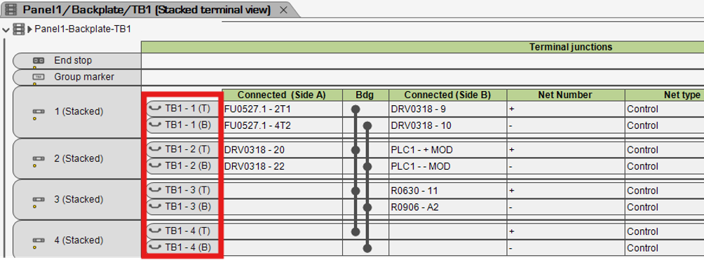
Remove bridges
The steps for removing bridges are the same as for adding bridges (above), but instead of selecting Add bridge, select Remove bridge.
Represent bridges with connections on schematics
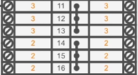
Bridges are shown in terminal strip layouts, which can be inserted onto schematics, thereby showing readers where bridges are installed, e.g. 11-13 and 14-16 are bridged:
If you would like to go a step further and show terminal bridges between the terminal symbols, you can do so with the Terminal Bridge/Jumper connection from the Terminals symbol library folder:
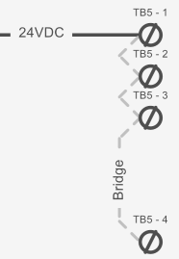
The dotted lines in the image above are the Terminal Bridge/Jumper connection.
Note: Drawing these connections does not add bridges in the terminal strip view.
Connected Side A and Connected Side B
By default, “Side A” is labeled “Exterior” and “Side B” is labeled “Interior”, so by default, in the terminal strip view, you will see Connected Exterior Side and Connected Interior Side columns.
“Interior” means in the same location as the terminal strip.
“Exterior” means not in the same location as the terminal strip.
If the terminal strip is an interface between two different locations, assign locations to the components where applicable.
Doing so should automatically populate many of the values in the Connected Exterior/Interior Side columns correctly (provided the Filter by locations property is checked).
Filter by locations automatically connects components on the correct side of the terminal junction based on where they are located, e.g. if the component is located in the same location as the terminal strip, it gets connected on the Connected Interior Side.
If the component is assigned to a different location than the terminal strip, it gets connected on the Connected Exterior Side.
Alternatively, if any terminals in the terminal strip are not an interface between two different locations, but are used for distribution within one location, turn off Filter by locations in the terminal strip properties to broaden connectivity possibilities.
Unresolved connectivity (connectivity information in parenthesis)
Unresolved connectivity is displayed as (TBD) for “To Be Defined” or connectivity information in parentheses.
For example, see the values in the Connected Exterior side and Connected Interior side columns below.

(TBD) means that port of the terminal junction could be connected to several different components, so it is not obvious to SkyCAD which component you would like that terminal junction port connected to.
When several terminals show the same connectivity information in parentheses, e.g. above, two terminal junction ports both show (FU1-2T1), it means any of those terminal junction ports can be connected to that component, but that only one needs to be connected to it.
There are two methods to resolve such unresolved connectivity information:
- Using the Resolve Connectivity command
- Using the Connect and Disconnect commands
Usually, we suggest using Resolve Connectivity first, then checking the results and using Connect and Disconnect to manually change any values as you see fit.
Note: When using Terminal Connection Point Blocks, connectivity is defined solely by the schematics, so you should never see unresolved connectivity with terminals represented by Terminal Connection Point Blocks.
‘Connect’ and ‘Disconnect’ commands
For any connectivity values which are/were (TBD) or connectivity information in parenthesis, you can use the Connect and Disconnect commands on these values to manually change the value.
To use these commands, select the Connected Side A/B (Connected Exterior Side and Connected Interior Side by default) cell for a terminal junction in the terminal strip view, go to the Terminal strip tools tab and select Connect or Disconnect, whichever you like.
If, after selecting Disconnect, you see connectivity information in parenthesis, select Disconnect again to remove the value.
If, after selecting Connect, a dialog box is displayed, it means there are several possible connection ports that terminal junction port can connect to. You can select the desired one and click OK or select several possibilities (hold CTRL or SHIFT + click) and click OK.
If you select Connect and nothing happens, it means there is no other valid option.
If you believe there should be, check the schematic to ensure the terminal is connected to the component connection port you believe it should be connected to.
The Filter by locations property may also be preventing you from achieving the desired result. (More about Filter by locations in the Introduction to terminal strips tutorial.)
Note: When using Terminal Connection Point Blocks the connectivity is defined solely by the schematics, so Connect and Disconnect do not affect terminals represented by Terminal Connection Point Blocks.
Flip terminal, junction, terminal strip
To flip connectivity results from one “Connected” column to the other “Connected” column, use whichever of the following methods suits your needs:
Flip terminal strip: Select the terminal strip, go to the Terminal strip tools tab and select Flip terminal strip. This turns on the Invert sides property in the terminal strip properties and flips the “Connected” column positions. This is purely cosmetic.
Flip terminal: Select a terminal in Single level view, go to the Terminal strip tools tab and select Flip terminal.
This flips the connectivity results for that terminal only.
This feature is not possible when Filter by locations is on and the terminal junction’s Flow Through property is checked (see the Flow Through section of the Introduction to terminal strips tutorial).
Flip junction: Select a terminal junction [e.g. TB1-1(T)] in Stacked terminal view, go to the Terminal strip tools tab and select Flip junction.
This flips the connectivity results for that terminal junction only.
This feature is not possible when Filter by locations is on and the terminal junction’s Flow Through property is checked (see the Flow Through section of the Introduction to terminal strips tutorial).
Show (N/C) for “Not Connected”
When a terminal junction is not connected to anything, the Connected Side A/B cell is simply blank.
If you would like to show (N/C) instead, select the terminal strip, go to the Terminal strip tools tab and select Show ‘(N/C)’ for not connected.
Efficient workflow summary
- Finish schematics, including OPRs and oriented connections (if you have an Advanced/Pro license)
- If the terminals are an interface between two different locations, assign locations to components.
If not, turn off Filter by locations. - Sort/group/move/rename terminals as desired
Ensure the terminal strip is assigned to the correct location/sub-location.
Run Wire Renumbering/Processing
Bridge junctions with same wire number
Resolve connectivity
Check connectivity and use Connect/Disconnect as needed
Related tutorials
Terminal strip layout (6:00)
Stacked terminals (3:35)
Numbering process (6:30)